Mustang 1994-1995 Export Taillight Installation
Introduction
Hello there! If you've arrived at my corner of the web, I presume you are looking for some info on installing export / eurostyle tail lights on a 1994 or 1995 Mustang. If you're looking for export taillight installation on a 1996 to 1998 Mustang, you would be better served
over here. If you are looking for Cobra tail light installation on a 1999 to 2001 Mustang, try
this page instead. I don't know of any export tail lights or resources for 1993 and earlier Mustangs, sorry.
I'm sure some of you are curious, what are export tail lights? Well, here in America cars are allowed to combine the brake lights and turn signals into the same bulbs. However, in Europe, Japan and possibly other areas around the world, cars are required to have their turn signals separate from their brake lights. On all 1994-2004 Mustangs (except 1999-2001 Cobras) in the US, the brake lights and turn signals are combined; so to sell the Mustang overseas Ford had to modify the tail lights to separate the turn signal. For the 1994-1995 "horizontal" tail lights, the turn signal takes the place of the reflector at the bottom of each tail light.
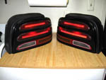
The image to the left shows a photo of a set of export tail lights (click it for a much larger image). As you can see, the reflector is replaced with a yellow strip. Also note that the reverse light does NOT have a red line throug the middle. This is an important feature to look for when buying export tail lights online. Depending on the camera angle and flash, the reflector part of the standard tails can sometimes look yellow.
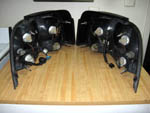
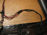
Here's the back side of the tails. When I got my first set from overseas, I was thrilled to see that they came with the tail light harness! This meant that I did not need to hack up my US harness to work with the export tails. This export harness adds one bulb for the turn signal, and cuts the turn signal feed from the two brake light bulbs. The corner bulb (only used when the headlights are on) and the reverse bulb are the same.
In my opinion, these tail lights create a unique look and as a bonus are OEM Ford parts; they look like they were meant to be on a Mustang.
How Do I Get A Set?
If you like these tails as much as I do, that's a good question. Sadly, these tail lights are fairly rare. You can find them occasionally on eBay, sometimes from international sellers but they rarely ship overseas. Be prepared to pay somewhere around $400 for a set (rare parts usually cost a lot), and they almost never have tail light harnesses. I have some access to Japanese auto part sites, so I can sometimes find 94-95 and 96-98 tail lights. Usually these tails have the tail light harness. I can sometimes get the export mirrors but can't get the export fender flares. Be aware that I cannot get these parts for cheap; Japanese sellers won't sell to overseas customers, so I have to use a service who will buy the parts for me. They charge for their services, of course. Shipping is really expensive too. So, while the tail lights themselves are usually about the same price as the US versions are over here, shipping and fees can push the price to $300 and up. You can contact me on the
StangNet Mustang board, I'm called "Chythar" there.
What Are The Differences Between The US and Export Harnesses?
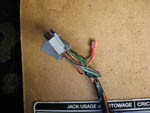
As stated before, the main difference is the export harness adds one bulb for the turn signal, and cuts the turn signal feed from the two brake light bulbs. Due to the extra bulb, the export harness has 5 wires in the connector instead of four. This means a new connector for the tail light harness is needed. See the
Parts and Tools List section below for a link on ordering the female connector to match the male connector on the export harness. These connectors are expensive, so you may decide to either modify your US harness or splice the US harness connector on to the export harness. I'd recommend modifying the US harness, because you could probably sell the export harness for a decent price; they're extremely rare, much more so than the export tail light housing itself. These instructions presume you have the female export connectors. Think about it - you've just spent $300 - $400 on a set of tail lights - what's an extra $40 to make it look like an OEM installation? To help you convert your US harness to an export one, here's a
comparison between the two harnesses.
Fortunately, the US and export harnesses use the same colors for their wires; the export harness adds a Red / Light Green stripe (R/LG) wire. This wire is for the separate brake feed. Having the other four wires match the US harness makes splicing in the export connector nice and easy - just match the colors. Be careful, there is a black wire and a black / pink stripe (BK/PK) wire - don't mix them up. Essentially, you'll splice into the four existing tail light connector wires and run a new red wire for the brake light.
Parts and Tools List
On to the installation! You will need the following parts to install the tail lights using my instructions. Since I have a set of tail light harnesses, these instructions will presume you have a set. These instructions do NOT require extra bulbs or resistors to fool the OEM turn signal/flasher.
- 1994-1995 Mustang export tail lights and harnesses (duh)
- One spool of 18-gauge wire (preferrably in red). You'll need 6-7 feet, I'd have more just in case.
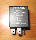
- One Tridon EP-27 "trailering" electronic flasher1
- Two Export harness connectors ($20 each, Motorcraft ID: WPT-343 or Ford ID: 3U2Z-14S411-KLA, found at National Fleet Parts or RockAuto)
- Heat shrink for 18 gauge wire, if you choose not to use the export harness connectors. If you want to be cheap, electrical tape will work too.
- Solderless Wire Quick Splice Connectors - 18-22 Gauge. I only used one, but you may need up to four depending on how you choose to splice the wiring.
- One pair of 16-22 gauge male & female disconnects (you may choose to skip these)
- Black electrical tape
You'll also need these tools:
- Soldering iron and standard rosin-core solder
- Heat gun for shrink-wrap
- Wire cutters
- Wire strippers
- Knife (I used an Xacto blade)
- Pry bar (useful for pulling out the plastic push-pins)
- Ratchet and sockets (size depends on the bolts used in your 'Stang)
- Screwdriver
1 The Tridon EP-27 "trailering" electronic flasher is the reason no extra bulbs or resistors are needed. The Ford OEM flasher unit checks the resistance of the wires to see if any of the bulbs are burned out. If the resistance is too low, the OEM flasher will blink twice as fast to let you know there is a problem. With this export tails installation, that is a problem since we are essentially removing a turn signal bulb. Remember, the OEM tail lights have two bulbs that do double-duty; brake lights and turn signals. As far as the wiring is concerned, you have two brake lights and two turn signals per side. It doesn't care that they are the same bulbs. The export tails split those duties into separate bulbs; two for brakes and one for the turn signal. This is why the OEM flasher unit thinks you are missing a bulb when you've actually added one.
This Tridon flasher unit was apparently designed for LED bulb replacements (as described
here), since the resistance on LEDs is really low. This works for us as well, since we're short a turn signal bulb on each side. The non-"trailering" unit is listed as a stock replacement for the 1994-2004 Mustang, among many other Ford and non-Ford cars. Be sure to get one that says "trailering" on the flasher unit or it won't work for this installation. As you can see in the photo, the word "trailering" is on the unit itself. It wasn't on the packaging nor did the clerk at the parts store I bought it from know anything about a "trailering" part. However, most online stores will list the part as EP-27 "trailering".
Be aware that the electronic flasher also makes the clicking noise that accompanies the turn signal flashing. Replacing the electronic flasher will change the noise and speed that the turn signal flashes. I found it to be a subtle change and got used to it quickly. If you really do not want to use the flasher, you can buy two 0.5 Ohm, 50 Watt resistors and put one in-line on the turn signal wire on each side. The turn signal comes in on the Light Green / Orange Stripe (LG/O) for the left turn signal, and on the Orange / Light Blue stripe (O/LB) for the right turn signal. The resistors will be quite hot, at least as hot as a bulb, so be careful where you mount them on the chassis. These instructions presume you use the Tridon "trailering" flasher.
Step 1: Stripping Out the Trunk Liners
If you already know how to remove the trunk liners, feel free to skip this step.
| 1. |
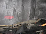
 First, you'll need to remove the plastic around the trunk latch. (Yes, I've replaced the trunk carpet with a nice gripper mat from Latemodel Restoration Supply) There are four plastic push-pins holding it in; one each on the far left and right sides, and one on either side of the latch itself. Use the pry bar to pop the push pins out and set the latch cover aside.
|
| 2. |
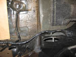
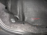 To remove the middle cover, you'll need to remove cargo net hooks on the left and right sides (left one pictured). It's threaded into one of the tail light bolts, so just unscrew both left and right hooks. The cover is now loose and with a bit of shifting around you can get it free of the trunk.
|
| 3. |
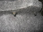
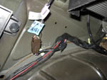
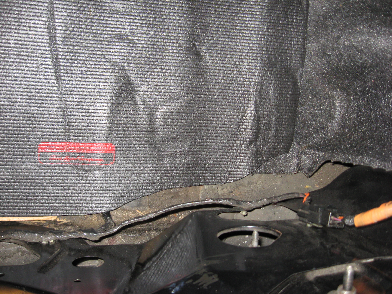
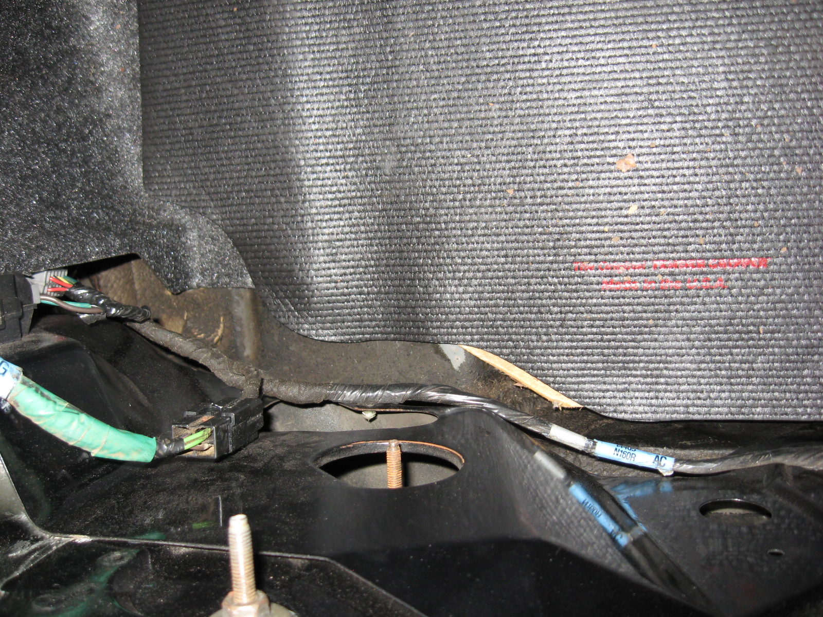
  These two photos show the middle cover removed and show the two tail light harness connectors. The harness runs from the right tail light over to the left, then plugs into the rest of the trunk wiring harness via the gray connector just barely visible on the left. Not showen is the middle of the harness, which is simply within a plastic cover.
|
| 4. |
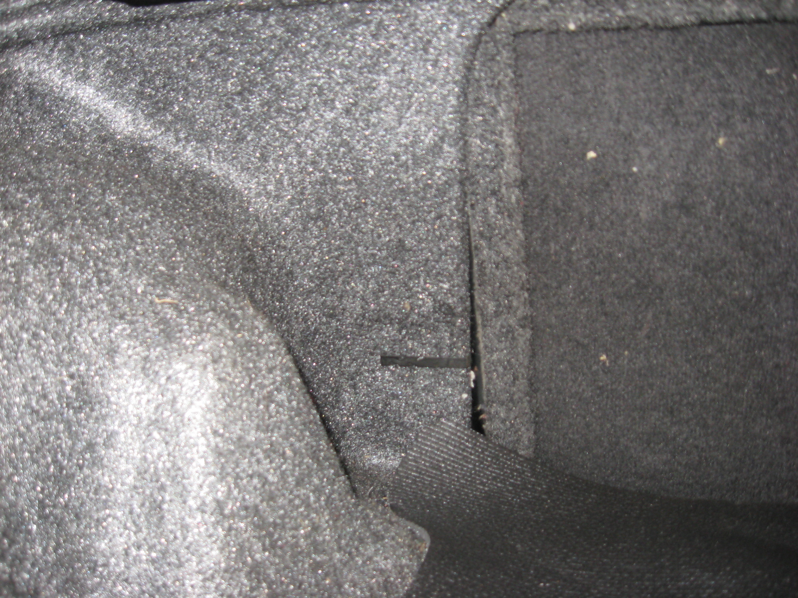
 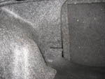 We'll have to remove the left trunk cover to get at the remaining wiring. We'll need to remove the right one later, to take out the tail light. To remove the right cover, you first need to remove the two nuts and the clip holding it into place. As seen in the photo, I have another cargo net hook in place of a nut. These are screwed into the long trunk hinge bolts, which go all the way through. Remove these nuts and set them aside. The second photo shows the clip holding the opposite edge of the trunk liner in place. I dropped the rear seats and used a screwdriver to pop it out. The liner is now free; slide the bottom towards the center of the trunk and it should pop out. Remove it from the trunk and set it aside.
|
Step 2: Splicing in the Export Tail Light Connectors
Be sure read all instructions before cutting wires! Save yourself some headache and frustration.
| 1. |
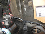
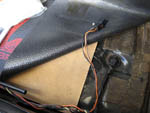 If you want an OEM look when you're done, you'll have to strip off the plastic covering the wiring harness. Disconnect both the left and right tail light connectors, along with the inertia switch and the large gray connector on the left side. Using your knife, carefully strip off all of the black plastic covering the wiring harness. Be aware that the fuel pump wiring is part of the harness on the right and does not disconnect from the harness inside the trunk. I choose to leave it connected and work around it. The photo shows the right tail light connector with the surrounding harness stripped.
|
| 2. |
Start with the right tail light connector. The export female connector has six wires in it, and we only need five. Plug the export tail light harness into the female connector, and it will be obvious which one you don't need. You can either cut off the extra wire, wrap it up with electrical tape, or be a masochist like me and unclip the extra wire out of the connector. To unclip the wire, you have to pop out a piece of plastic on the back of the connector, then use a small screwdriver to try and push up a small clip holding the wire in place. Man, what a PITA. |
| 3. |
Leave the export harness plugged in for now. The export female connector conveniently comes with double-walled heat shrink, one for each wire. Since we're only using five of the six wires, you'll have two total left over. The instructions say to start your first splice about 3" from the connector, and to stagger them so the harness doesn't get too thick in one place. I found that I had some overlap, sometimes two splices in about the same place. The shrink wrap'd joins were pretty thin, so two in one place isn't bad. Note that the chassis harness takes a 90° bend not far from the connector, with a harness plastic push-pin right afterwards. I started my first splice a bit after that bend, right where the push-pin is, then staggered them as best as I could. You may want to put some colored tape on the export connector wires so you don't mix up the wires. I just cut, spliced and soldered one wire at a time. Be careful, there is a black wire and a black / pink stripe (BK/PK) wire - don't mix them up. The one export wire not handled by the factory harness is the Red / Light Green stripe (R/LG) wire. Take your spool of 18-gauge red wire and splice it into the export connector wire. You'll need enough wire to reach all the way over to the gray connector all the way on the left; I just left the spool hooked up for now. |
| 4. |
Plan where to cut your wires. Use your best judgement on where to cut and solder the joints. If you need some advice, the soldering instructions in the pamphlet that comes with the export connectors will work just fine. BE ABSOLUTELY SURE to slide a piece of shrink wrap on the wire before joining and soldering the wires! If you don't, you're going to have to un-solder the wires or pop the wire out of the export connector (refer to the earlier mention of being a major PITA). On the brown and black / pink stripe (BK/PK) wires, you may want to slide TWO pieces of shrink wrap on. The joins on the left side splice into an unbroken wire, so you should slide the shrink wrap on now. You can also pop the far-left gray connector apart (much easier than doing the same on the export connector), but it won't work if you've already soldered to those wires. You'll then have to pop the wires out of the right export connector. In my case, my heat shrinked joins were small enough I could slide the un-shrunk wrap over those joins. |
| 5. |
Note: You may want to test the wiring as you go along, especially before you put on the heat shrink. Two things will be incomplete; the brake will light the turn signal bulb instead of the brakes, and the flasher unit will blink twice as fast (due to having one bulb instead of two). Both of these will be taken care of in later steps. But this will test that your soldered splices are working correctly. I was able to check the lights on my own by dropping the back seats and setting the tail light harnesses in the trunk so I could see all the bulbs. |
| 6. |
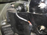
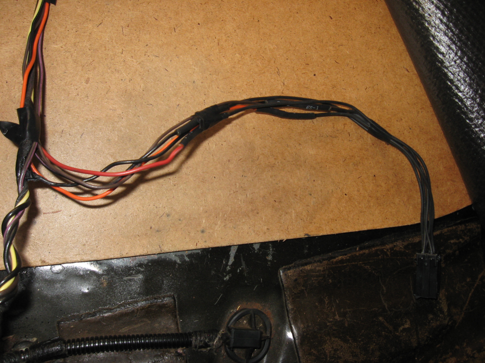
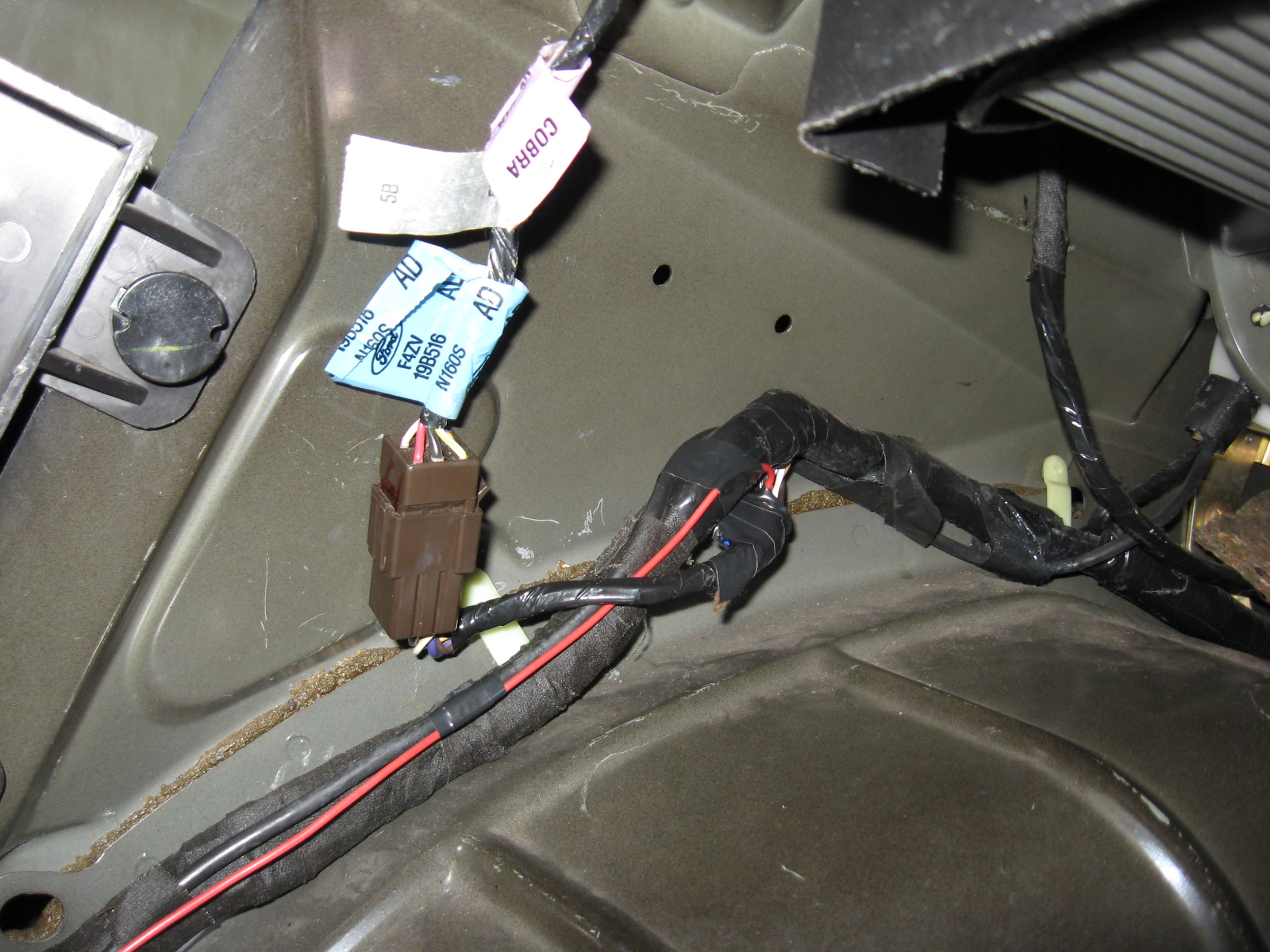
 Again, be VERY CAREFUL about which wires you cut and splice. If in doubt, make the wire too long. The photo shows my completed wiring harness for the right tail light. I made my harness the same length as the OEM harness, but there was enough wire left over that I could have added another inch to the harness if I chose to.
|
| 7. |
 This photo shows the nearly-complete left harness. Note the heat-shrinked splices at the bottom. You'll need to run the red wire all the way over to the left side, of course. You can also see I wrapped a bit of electrical tape around the wires every few inches. This was done to make sure I didn't pull any of the wires too tight and bunch up the harness. To hook up the Red / Light Green stripe (R/LG) wire on the left connector to the red wire, I stripped some of the plastic off of the red wire and spliced the wire directly in. Again, do not forget to slide the heat shrink on before soldering! In this example, I forgot to do just that and had to pop the red wire out of the right connector and slide the heat shrink all the way over. I had to do this several times throughout the job.
|
| 8. |
 At this point, the wiring should be nearly complete. All that's left is the red wire for the brakes. This we will splice into the line from the third brake light. I next chose to add a male/female disconnect to the red wire, right at the gray connector. The gray connector has several empty slots; if I had the right kind of terminals, I could plug the red wire right into the gray connector for an OEM appearance. Since I didn't have the right terminals, I just used a male/female pair of 18-gauge disconnects. I find it unlikely that I'd need to unplug this harness EVER, but it would bug me not to have that disconnect pair there. I cut the red wire and crimped on one of the disconnects (I chose female to match the gray connector, but it doesn't matter which) After crimping one of the disconnects on, hold off on the other one. We'll add it in the next step.
 |
Step 3: Tapping The Brake Feed From The Third Brake Light
| 1. |
 As stated, we'll be tapping the brake feed from the third brake light. The trunk lid harness meets the main harness on the left side, not far below the hinge for the lid. You can see the plastic holder for the anti-theft & keyless entry modules on the left. If you're not sure, you can just follow the trunk lid harness down until you see it. We'll be tapping the brake feed before the connector. Split the plastic covering the harness to reveal the wires. You want to tap the Red / Light Green stripe (R/LG) wire. Sound familiar? That's the same color as the brake feed in the export tail light harness. You'll find two R/LG wires there; pick either one, they both join up in the trunk lid connector anyway. This section of wiring was really hard for me to get into, so instead of splicing and soldering I used a quick-splice connector I had lying around. Slip it over the R/LG wire, slide the end of the red wire in, and squeeze it with a pair of pliers.
|
| 2. |
 Go ahead and wrap the exposed wires up, along with the quick-splice connector. Run the red wire down the trunk harness, using electrical tape every few inches or so to hold the wire against the harness. Follow the harness all the way to the gray connector from step 2. Cut the red wire a bit long, the crimp the other 18-gauge disconnect on to that wire. Plug the two disconnects together to complete the circuit. You can now test the brake lights, they should work as expected. Also turn on the headlights and make sure all bulbs light as expected. You should notice two problems: the turn signals blink twice as fast, and the turn signals light up with the brakes. We'll tackle those next.
|
Step 4: Replacing the Flasher Unit
| 1. |
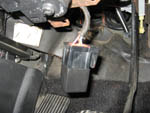
 Let's fix that annoying double-blinking. This is really easy, just swap out the OEM flasher with the Tridon "trailering" unit. The OEM flasher unit is found right behind the under-dash fuse box, as seen in the photo here. (stupid camera, focusing on the background instead of the flasher)
|
| 2. |
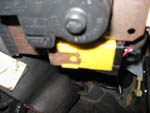
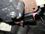
 The flasher just slides off the metal tab. Unplug the connector and plug the Tridon unit in. The metal prongs on the flasher will only allow it to be installed one way. Be careful, I somehow managed to slice my thumb open when pulling the OEM flasher off the metal tab. Didn't realize it until I noticed blood all over the OEM flasher. The photo here shows the Tridon plugged into the connector, and I think that's a bit of blood too. I thought it was only engine work that required busted knuckles and a donation of blood...
|
| 3. |
 The Tridon flasher doesn't have a clip to hold it on to the metal clip, but the photo shows a zip tie holds it nice and tight. Be aware that the clicking noise from the turn signals is made from the flasher unit, so with the Tridon in place your turn signals will sound different and may blink at a slightly different rate. In my case, I noticed a slight delay in blinking the first time I turned on either turn signal, but it went away after that one time. Seems to happen every time you turn the key on. I also noticed the blinking being a bit slower than the OEM blinker. But the best part, that makes me forgive both those issues? No double-blinking! The turn signals blink at a steady rate now.
|
Step 5: Remove The Brake Feed From The Turn Signals
| 1. |
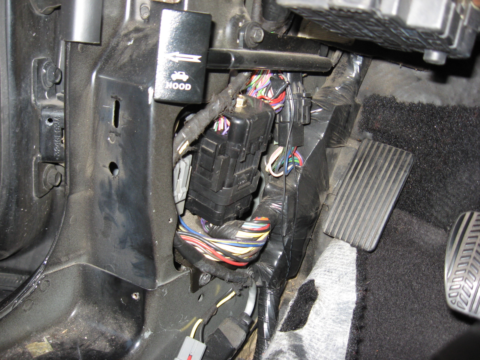
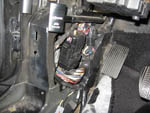 Last modification to the wiring harness: cutting the brake feed from the turn signals. I give all the credit for this part to MW98GT, from his Mustang Eurostyle Taillight Installation (96-98 export tails install). You'll cut the feed right at the main distribution block behind the driver's kick panel. To get at the distribution block, pull up the driver's side door sill plastic. Use a screwdriver to pry any metal clips off the pinch weld and push them back on the underside of the door sill plastic; this makes installation much easier. Pull the one plastic push-pin out, from the side of the kick panel, then the kick panel will just slide up and towards you. You will then see what's in the photo. Remove the bolt below the distribution block, which will free up the bracket and allow you to rotate the distribution block out. I found I could rotate the distribution block out farther after unbolting the hood release pull.
|
| 2. |
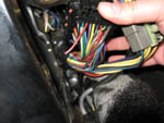
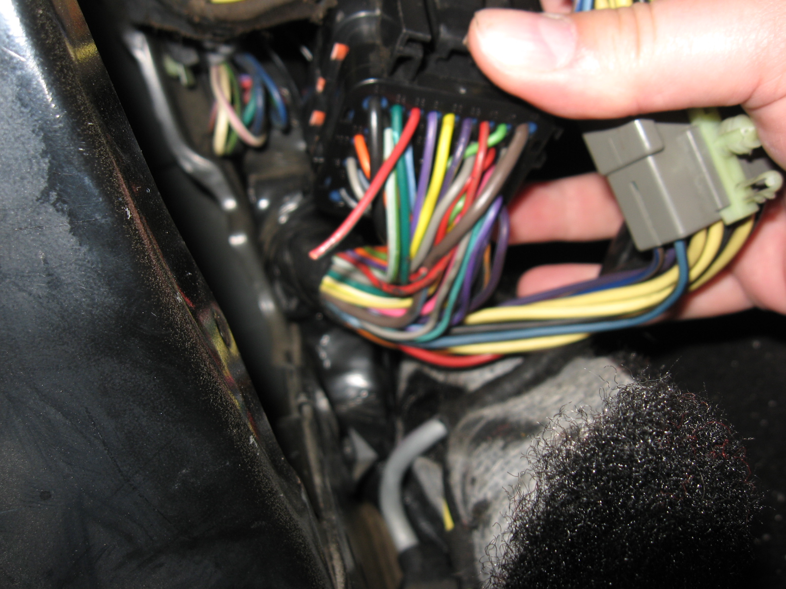
 This photo is from the back ofthe distribution block, the bracket it's mounted on is clearly visible. There are two red wires visible at the back of hte distribution block; both are Red / Light Green stripe (R/LG) wires, and both lead back down the harness to the third brake light harness from step 3. According to my Ford EVTM manual, both R/LG come from the brake switch, but one R/LG routes into the multifunction switch (to send the brake signal to the turn signals) and the other routes to the computer. If you cut the one going to the computer, you will cut out ALL brake light signals but the turn signal will still light when you hit the brakes. The one you want to cut is the closest wire in the photo, with the visible green stripe. To be absolutely safe, cut the wire at least an inch away from the distribution block. If you cut the wrong wire, or for some reason want to reinstall the OEM lights, you have enough wire to solder in a patch and restore the connection.
|
| 3. |
 This last photo for step 5 shows the correct wire cut. I removed the distribution block from its bracket to be absolutely sure I had the right wire. Fortunately for me, I cut the right wire and my turn signals no longer light when I press the brake pedal. Congratulations! You've completed all of the wiring modifications! Wrap both ends of the wire you cut in electrical tape to avoid electrical shorts, then clip the distribution block back on its bracket. Slip the distribution block back into place and bolt the bracket and hood release pull back in place. Reinstall the kick panel, then line up the door sill plastic and push it into place.
|
Step 6: Re-wrap The Trunk Wiring Harness
| 1. |
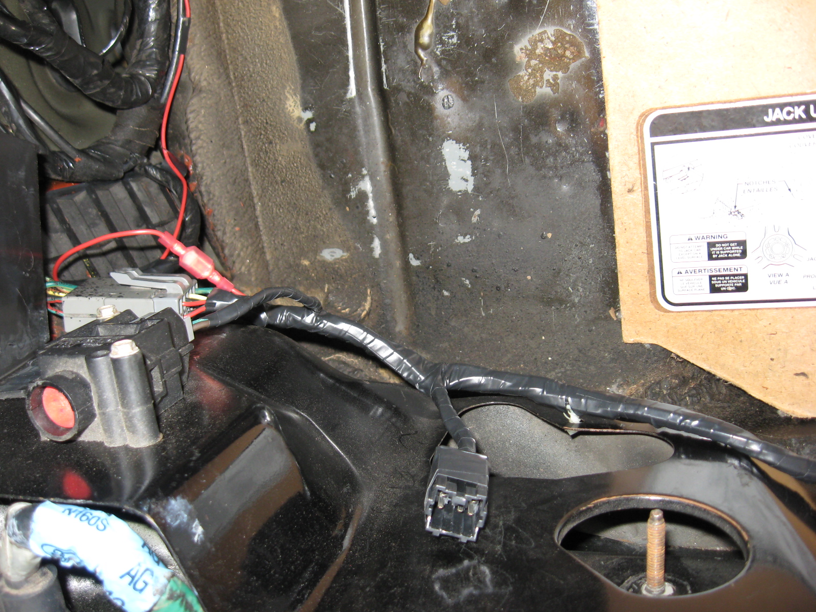
  Time to wrap the rear harness in electrical tape. These two photos show the finished harness. I wrapped both tail light connector wires and the inertia switch wires first, until they met the main harness. Now, what you don't see in the middle is a plastic cover for the wiring under the trunk latch. To match the OEM look, I wrapped the wiring from the outer edges first; starting at thr fuel pump wires and wrapping inwards until it met the plastic cover in the center. I repeated this process on the other side, from the gray connector until it met the plastic cover in the center. Plug the gray connector and the red disconnects together on the left to complete the tail light chassis harness.
|
Step 7: Swap Out The Tail Lights
| 1. |
  Before removing the tail lights themselves, make one last check with the export tail light harnesses. Check that all bulbs work as expected, replace any bulbs that are burned out. It would suck if you finished the job and then found out a bulb was not working. To remove the tail lights, remove the four nuts holding them into place. The photos show the nuts on the long bolts coming from the tail lights. Once the nuts have been removed, push the rubber seal around the tail light harness in so it's loose. Pull the tail light free slowly, guiding the tail light harness plug out of the hole in the chassis. Repeat this process for the other tail light.
|
| 2. |
Install the export tail light harness into the export tail light housing, making sure to install the right bulbs in the right sockets. Once all the bulbs are locked into place, slide the tail light harness connector back through the same hole the old harness came from and slide the loing bolts in the housing through the same holes in the chassis. Plug the tail light connectors together to finish the wiring. At this point, I did yet another sanity check and checked all of the lights once again. Yes, I admit it; I'm paranoid about electrical wiring. I'd rather triple- and quadruple-check everything, because it seems when I don't I end up with a short that takes me hours to find. After verifying the lights yet again, finger-tighten the nuts down so the tail lights aren't loose. Close the trunk lid and check the alignment of the tail lights to the bumper and the trunk. You may need to use spacers on some of the tail light bolts to get the alignment just right (I did). When you're satisfied with the alignment, tighten the four nuts down on each tail light. Be sure to pull the rubber seal on the tail light harness through the hole until it pops into place.
|
| 3. |
Replace the trunk liners and the plastic trunk latch cover. If you don't remember how, go back to step 1 and reverse the instructions.
|
DONE!
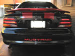
Finally! Your tail lights should look like these. Time to buff out the plastic (especially if they're hazed or foggy) and put a coat of wax on them. Congratulations on a job well done!
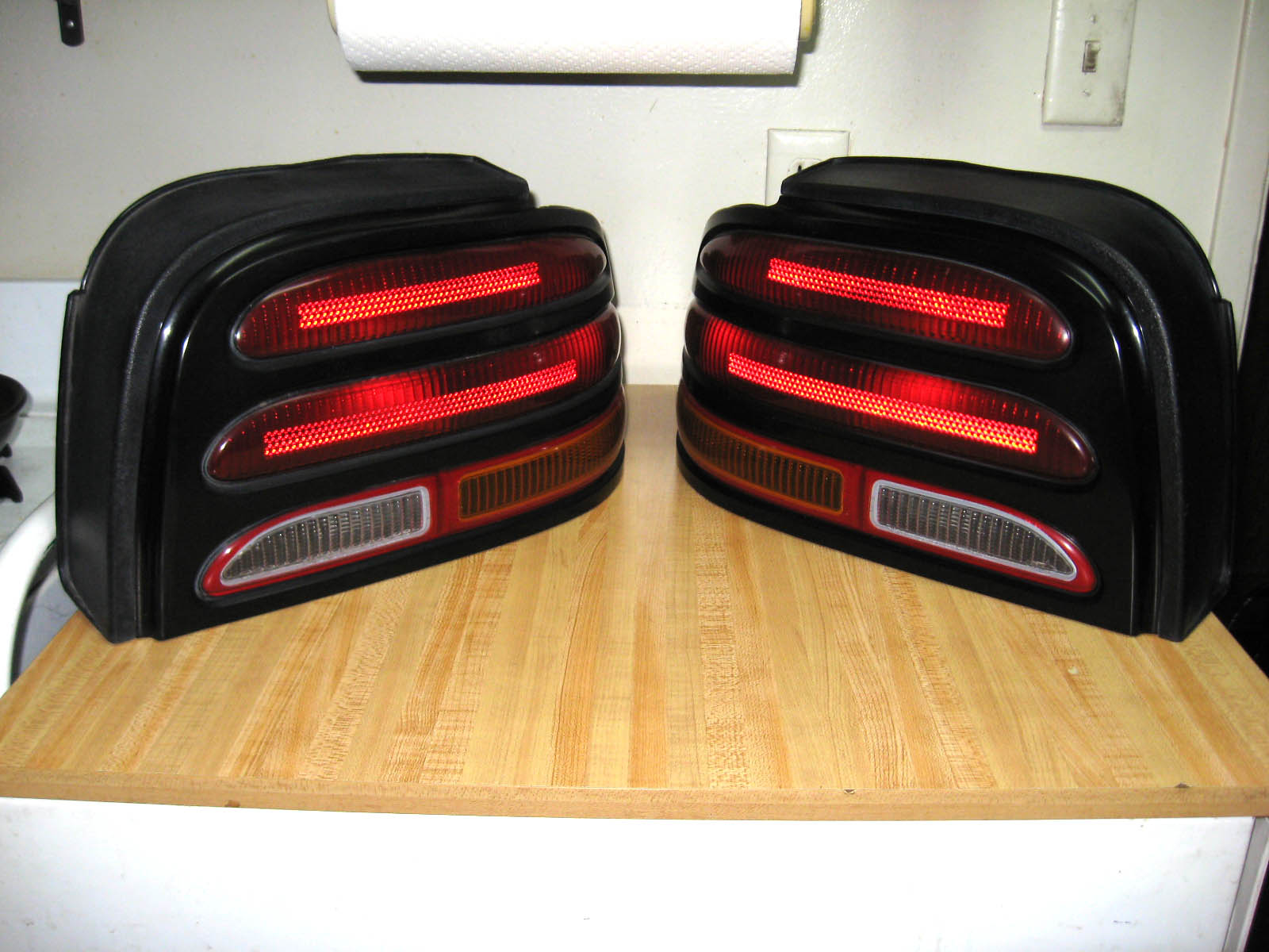 The image to the left shows a photo of a set of export tail lights (click it for a much larger image). As you can see, the reflector is replaced with a yellow strip. Also note that the reverse light does NOT have a red line throug the middle. This is an important feature to look for when buying export tail lights online. Depending on the camera angle and flash, the reflector part of the standard tails can sometimes look yellow.
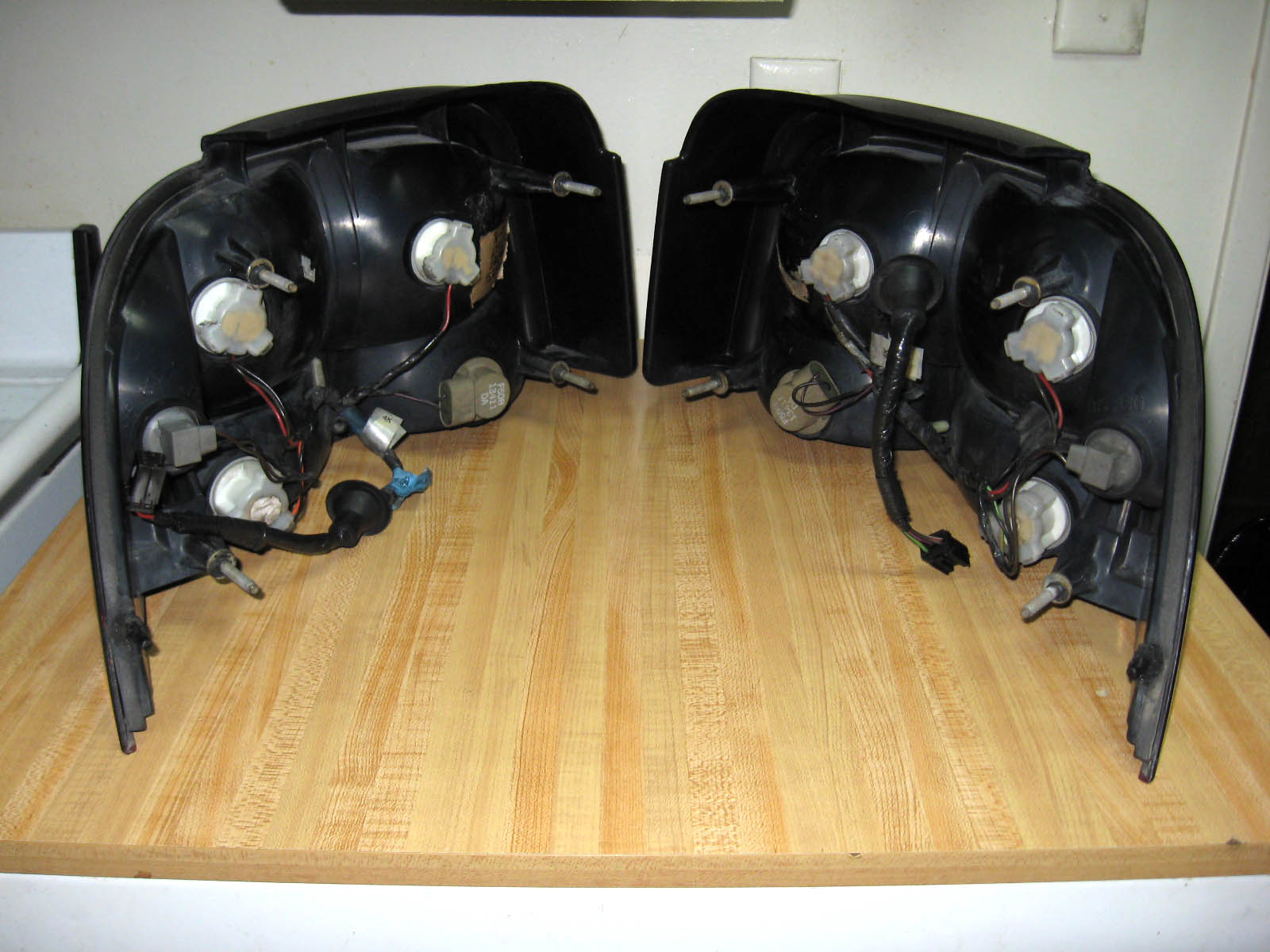 Here's the back side of the tails. When I got my first set from overseas, I was thrilled to see that they came with the tail light harness! This meant that I did not need to hack up my US harness to work with the export tails. This export harness adds one bulb for the turn signal, and cuts the turn signal feed from the two brake light bulbs. The corner bulb (only used when the headlights are on) and the reverse bulb are the same.
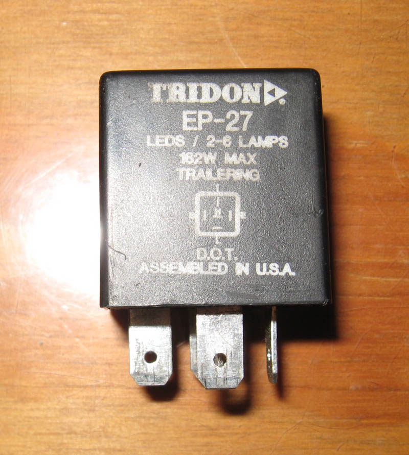 This Tridon flasher unit was apparently designed for LED bulb replacements (as described here), since the resistance on LEDs is really low. This works for us as well, since we're short a turn signal bulb on each side. The non-"trailering" unit is listed as a stock replacement for the 1994-2004 Mustang, among many other Ford and non-Ford cars. Be sure to get one that says "trailering" on the flasher unit or it won't work for this installation. As you can see in the photo, the word "trailering" is on the unit itself. It wasn't on the packaging nor did the clerk at the parts store I bought it from know anything about a "trailering" part. However, most online stores will list the part as EP-27 "trailering".
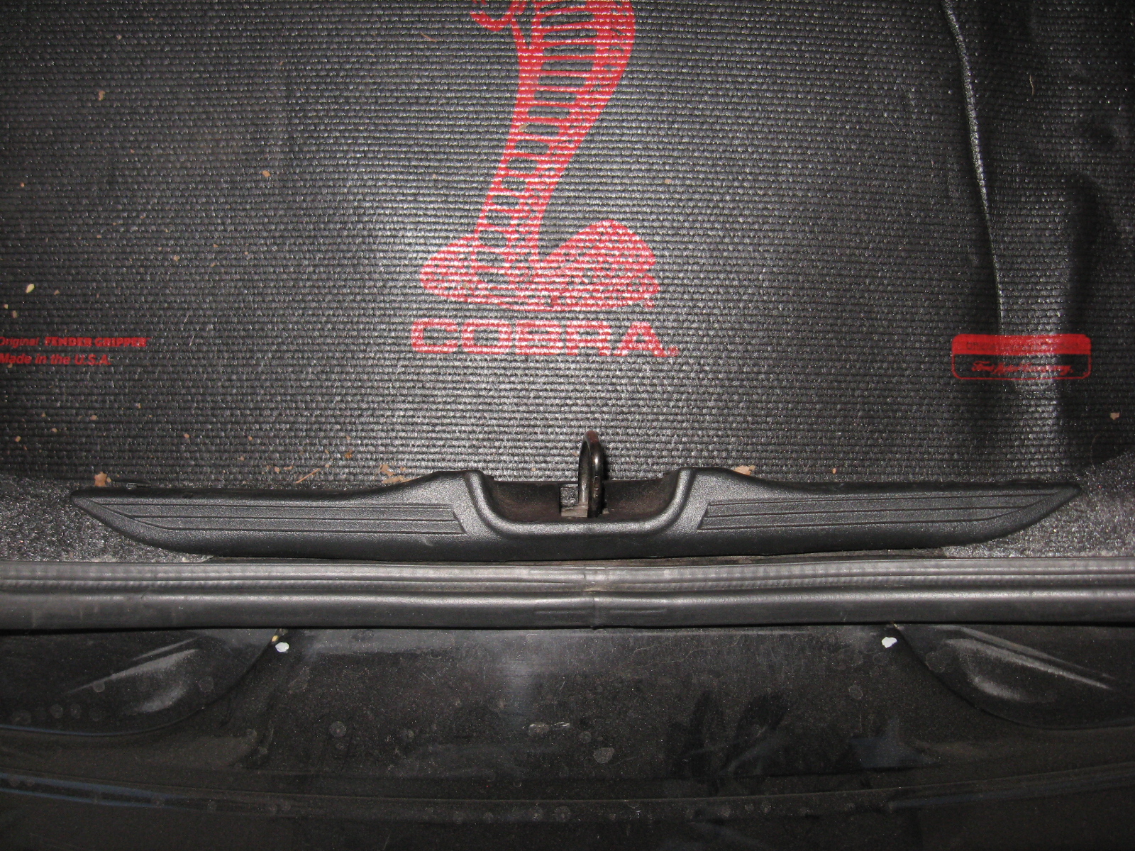 First, you'll need to remove the plastic around the trunk latch. (Yes, I've replaced the trunk carpet with a nice gripper mat from Latemodel Restoration Supply) There are four plastic push-pins holding it in; one each on the far left and right sides, and one on either side of the latch itself. Use the pry bar to pop the push pins out and set the latch cover aside.
 To remove the middle cover, you'll need to remove cargo net hooks on the left and right sides (left one pictured). It's threaded into one of the tail light bolts, so just unscrew both left and right hooks. The cover is now loose and with a bit of shifting around you can get it free of the trunk.
 These two photos show the middle cover removed and show the two tail light harness connectors. The harness runs from the right tail light over to the left, then plugs into the rest of the trunk wiring harness via the gray connector just barely visible on the left. Not showen is the middle of the harness, which is simply within a plastic cover.

 We'll have to remove the left trunk cover to get at the remaining wiring. We'll need to remove the right one later, to take out the tail light. To remove the right cover, you first need to remove the two nuts and the clip holding it into place. As seen in the photo, I have another cargo net hook in place of a nut. These are screwed into the long trunk hinge bolts, which go all the way through. Remove these nuts and set them aside. The second photo shows the clip holding the opposite edge of the trunk liner in place. I dropped the rear seats and used a screwdriver to pop it out. The liner is now free; slide the bottom towards the center of the trunk and it should pop out. Remove it from the trunk and set it aside.
 If you want an OEM look when you're done, you'll have to strip off the plastic covering the wiring harness. Disconnect both the left and right tail light connectors, along with the inertia switch and the large gray connector on the left side. Using your knife, carefully strip off all of the black plastic covering the wiring harness. Be aware that the fuel pump wiring is part of the harness on the right and does not disconnect from the harness inside the trunk. I choose to leave it connected and work around it. The photo shows the right tail light connector with the surrounding harness stripped.
 Again, be VERY CAREFUL about which wires you cut and splice. If in doubt, make the wire too long. The photo shows my completed wiring harness for the right tail light. I made my harness the same length as the OEM harness, but there was enough wire left over that I could have added another inch to the harness if I chose to.
 This photo shows the nearly-complete left harness. Note the heat-shrinked splices at the bottom. You'll need to run the red wire all the way over to the left side, of course. You can also see I wrapped a bit of electrical tape around the wires every few inches. This was done to make sure I didn't pull any of the wires too tight and bunch up the harness. To hook up the Red / Light Green stripe (R/LG) wire on the left connector to the red wire, I stripped some of the plastic off of the red wire and spliced the wire directly in. Again, do not forget to slide the heat shrink on before soldering! In this example, I forgot to do just that and had to pop the red wire out of the right connector and slide the heat shrink all the way over. I had to do this several times throughout the job.
 At this point, the wiring should be nearly complete. All that's left is the red wire for the brakes. This we will splice into the line from the third brake light. I next chose to add a male/female disconnect to the red wire, right at the gray connector. The gray connector has several empty slots; if I had the right kind of terminals, I could plug the red wire right into the gray connector for an OEM appearance. Since I didn't have the right terminals, I just used a male/female pair of 18-gauge disconnects. I find it unlikely that I'd need to unplug this harness EVER, but it would bug me not to have that disconnect pair there. I cut the red wire and crimped on one of the disconnects (I chose female to match the gray connector, but it doesn't matter which) After crimping one of the disconnects on, hold off on the other one. We'll add it in the next step.
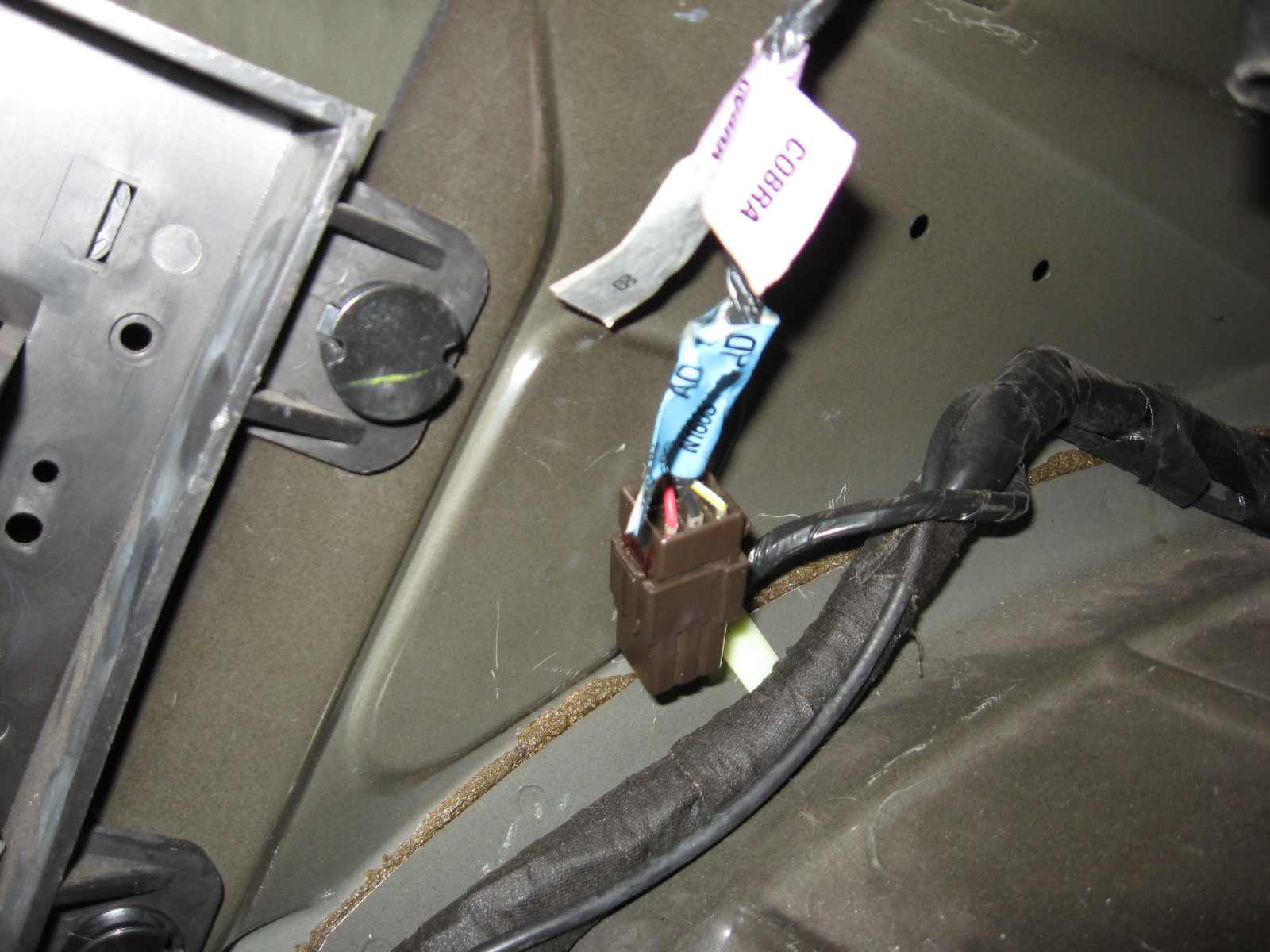 As stated, we'll be tapping the brake feed from the third brake light. The trunk lid harness meets the main harness on the left side, not far below the hinge for the lid. You can see the plastic holder for the anti-theft & keyless entry modules on the left. If you're not sure, you can just follow the trunk lid harness down until you see it. We'll be tapping the brake feed before the connector. Split the plastic covering the harness to reveal the wires. You want to tap the Red / Light Green stripe (R/LG) wire. Sound familiar? That's the same color as the brake feed in the export tail light harness. You'll find two R/LG wires there; pick either one, they both join up in the trunk lid connector anyway. This section of wiring was really hard for me to get into, so instead of splicing and soldering I used a quick-splice connector I had lying around. Slip it over the R/LG wire, slide the end of the red wire in, and squeeze it with a pair of pliers.
 Go ahead and wrap the exposed wires up, along with the quick-splice connector. Run the red wire down the trunk harness, using electrical tape every few inches or so to hold the wire against the harness. Follow the harness all the way to the gray connector from step 2. Cut the red wire a bit long, the crimp the other 18-gauge disconnect on to that wire. Plug the two disconnects together to complete the circuit. You can now test the brake lights, they should work as expected. Also turn on the headlights and make sure all bulbs light as expected. You should notice two problems: the turn signals blink twice as fast, and the turn signals light up with the brakes. We'll tackle those next.
 Let's fix that annoying double-blinking. This is really easy, just swap out the OEM flasher with the Tridon "trailering" unit. The OEM flasher unit is found right behind the under-dash fuse box, as seen in the photo here. (stupid camera, focusing on the background instead of the flasher)
 The flasher just slides off the metal tab. Unplug the connector and plug the Tridon unit in. The metal prongs on the flasher will only allow it to be installed one way. Be careful, I somehow managed to slice my thumb open when pulling the OEM flasher off the metal tab. Didn't realize it until I noticed blood all over the OEM flasher. The photo here shows the Tridon plugged into the connector, and I think that's a bit of blood too. I thought it was only engine work that required busted knuckles and a donation of blood...
 The Tridon flasher doesn't have a clip to hold it on to the metal clip, but the photo shows a zip tie holds it nice and tight. Be aware that the clicking noise from the turn signals is made from the flasher unit, so with the Tridon in place your turn signals will sound different and may blink at a slightly different rate. In my case, I noticed a slight delay in blinking the first time I turned on either turn signal, but it went away after that one time. Seems to happen every time you turn the key on. I also noticed the blinking being a bit slower than the OEM blinker. But the best part, that makes me forgive both those issues? No double-blinking! The turn signals blink at a steady rate now.
 Last modification to the wiring harness: cutting the brake feed from the turn signals. I give all the credit for this part to MW98GT, from his Mustang Eurostyle Taillight Installation (96-98 export tails install). You'll cut the feed right at the main distribution block behind the driver's kick panel. To get at the distribution block, pull up the driver's side door sill plastic. Use a screwdriver to pry any metal clips off the pinch weld and push them back on the underside of the door sill plastic; this makes installation much easier. Pull the one plastic push-pin out, from the side of the kick panel, then the kick panel will just slide up and towards you. You will then see what's in the photo. Remove the bolt below the distribution block, which will free up the bracket and allow you to rotate the distribution block out. I found I could rotate the distribution block out farther after unbolting the hood release pull.
 This photo is from the back ofthe distribution block, the bracket it's mounted on is clearly visible. There are two red wires visible at the back of hte distribution block; both are Red / Light Green stripe (R/LG) wires, and both lead back down the harness to the third brake light harness from step 3. According to my Ford EVTM manual, both R/LG come from the brake switch, but one R/LG routes into the multifunction switch (to send the brake signal to the turn signals) and the other routes to the computer. If you cut the one going to the computer, you will cut out ALL brake light signals but the turn signal will still light when you hit the brakes. The one you want to cut is the closest wire in the photo, with the visible green stripe. To be absolutely safe, cut the wire at least an inch away from the distribution block. If you cut the wrong wire, or for some reason want to reinstall the OEM lights, you have enough wire to solder in a patch and restore the connection.
 This last photo for step 5 shows the correct wire cut. I removed the distribution block from its bracket to be absolutely sure I had the right wire. Fortunately for me, I cut the right wire and my turn signals no longer light when I press the brake pedal. Congratulations! You've completed all of the wiring modifications! Wrap both ends of the wire you cut in electrical tape to avoid electrical shorts, then clip the distribution block back on its bracket. Slip the distribution block back into place and bolt the bracket and hood release pull back in place. Reinstall the kick panel, then line up the door sill plastic and push it into place.

 Time to wrap the rear harness in electrical tape. These two photos show the finished harness. I wrapped both tail light connector wires and the inertia switch wires first, until they met the main harness. Now, what you don't see in the middle is a plastic cover for the wiring under the trunk latch. To match the OEM look, I wrapped the wiring from the outer edges first; starting at thr fuel pump wires and wrapping inwards until it met the plastic cover in the center. I repeated this process on the other side, from the gray connector until it met the plastic cover in the center. Plug the gray connector and the red disconnects together on the left to complete the tail light chassis harness.

 Before removing the tail lights themselves, make one last check with the export tail light harnesses. Check that all bulbs work as expected, replace any bulbs that are burned out. It would suck if you finished the job and then found out a bulb was not working. To remove the tail lights, remove the four nuts holding them into place. The photos show the nuts on the long bolts coming from the tail lights. Once the nuts have been removed, push the rubber seal around the tail light harness in so it's loose. Pull the tail light free slowly, guiding the tail light harness plug out of the hole in the chassis. Repeat this process for the other tail light.
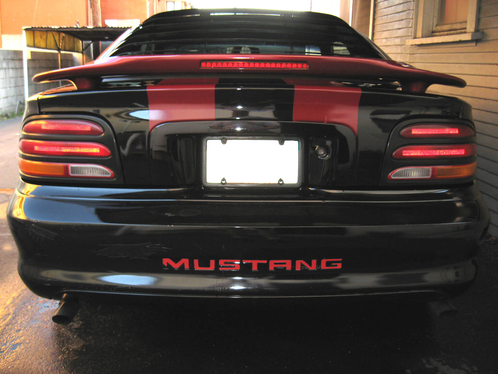 Finally! Your tail lights should look like these. Time to buff out the plastic (especially if they're hazed or foggy) and put a coat of wax on them. Congratulations on a job well done!